Pre-beam work: circ raster with the Hall C waveform
From SBS wiki
9/12/22
This is how the raster output is processed:
- The voltage output from the 4 raster coils is sent to 4 FADC channels in one FADC that resides in the a crate in the SBS bunker and in another FADC that sits in a crate in the LHRS hut.
- The FADCs are ran in pulse mode (mode 7).The FADC running parameters are:
FADC250_SLOT 14 - LHRS (in sbs-onl@halladaq8 /home/sbs-onl/cfg/fadc250/halladaq8.cnf) and FADC250_SLOT 20 - SBS (in sbs-onl@sbsvme29 /home/sbs-onl/cfg/fadc250/sbsvme29.cnf)

FADC250_MODE      7
FADC250_W_OFFSET  1650 (in ns)
FADC250_W_WIDTH   400 (in ns)
FADC250_NSB 4 (in ns)
FADC250_NSA 99 (in ns)
FADC250_NPEAK 1 (nr of peaks to keep)
FADC250_TET 1
FADC250_DAC 2200
FADC250_PED  1
FADC250_GAIN 1
channel:  0  1  2  3  4  5  6  7  8  9 10 11 12 13 14 15
FADC250_ADC_MASK  1  1  1  1  1  1  1  1  1  1  1  1  1  1  1  1
FADC250_TRG_MASK  1  1  1  1  1  1  1  1  1  1  1  1  1  1  1  1
- Once the replay is ran the FADC pulse integral per channel ends up in the root tree under:
 Lrb.Raster.rawcur.x, Lrb.Raster.rawcur.y, Lrb.Raster.rawcur2.x, Lrb.Raster.rawcur2.y for LHRS
 SBSrb.Raster.rawcur.x, SBSrb.Raster.rawcur.y, SBSrb.Raster2.rawcur.x, SBSrb.Raster2.rawcur.y for SBS
- What is called rawcur is actually the sum over the NSA+NSB FADC samples in units of FADC channels, where NSA and NSB are specified in the crl code. To get the "pulse" integral in units of C one must use a conversion factor which includes the dynamical range of the FADC as set by user (2 V I am told, I will check next time when I start a run in the appropriate DAQ ROC), the number of FADC channels, the resistance of the FADC and the time between samples (4 ns) - see below for the exact formula of the conversion factor.
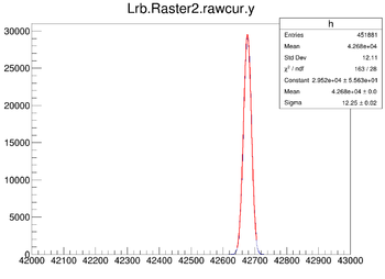
- The pedestals for the LHRS/SBS FADC channels are (meaning no current on the raster coils):
- The code circRaster.C will loop through the number of entries in these branches and:
 if(PlotInMM){
         lhrs_x1 = (Lrb_raster1_rawcur_x - offset)*conv;
         lhrs_y1 = (Lrb_raster1_rawcur_y - offset)*conv;
         lhrs_x2 = (Lrb_raster2_rawcur_x - offset)*conv;
         lhrs_y2 = (Lrb_raster2_rawcur_y - offset)*conv;
         sbs_x1  = (SBSrb_raster1_rawcur_x - offset)*conv;
         sbs_y1  = (SBSrb_raster1_rawcur_y - offset)*conv;
         sbs_x2  = (SBSrb_raster2_rawcur_x - offset)*conv;
         sbs_y2  = (SBSrb_raster2_rawcur_y - offset)*conv;

 if(SmearWithBeam){
            bx = myRand->Gaus(beamCenter,beamWidth);
            by = myRand->Gaus(beamCenter,beamWidth);
	    lhrs_x1 += bx;
	    lhrs_y1 += by;
	    lhrs_x2 += bx;
	    lhrs_y2 += by;
	    sbs_x1  += bx;
	    sbs_y1  += by;
	    sbs_x2  += bx;
	    sbs_y2  += by;
	    sbs_y2  += by;
	 }

where:

* "offset" is the pedestal
* "conv" is a factor that takes us from units of FADC raw integral to mm

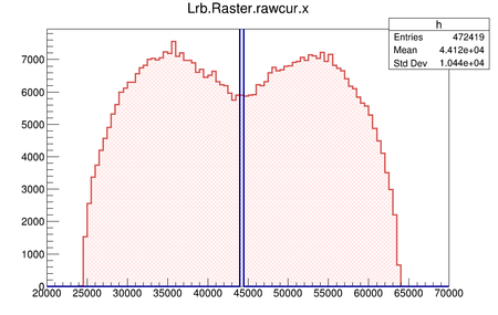
For example, in the case shown in Fig. below "conv" will be 3.0/(64000 - 44000), where 3 is half the desired raster size in mm, 64000 is the highest FADC raw integral with current on the raster coils and 44000 is the pedestal.

 }else{
	lhrs_x1 = (Lrb_raster1_rawcur_x - offset)*conv_to_nC;
	lhrs_y1 = (Lrb_raster1_rawcur_y - offset)*conv_to_nC;
	lhrs_x2 = (Lrb_raster2_rawcur_x - offset)*conv_to_nC;
	lhrs_y2 = (Lrb_raster2_rawcur_y - offset)*conv_to_nC;
	sbs_x1  = (SBSrb_raster1_rawcur_x - offset)*conv_to_nC;
	sbs_y1  = (SBSrb_raster1_rawcur_y - offset)*conv_to_nC;
	sbs_x2  = (SBSrb_raster2_rawcur_x - offset)*conv_to_nC;
	sbs_y2  = (SBSrb_raster2_rawcur_y - offset)*conv_to_nC;


where conv_to_nC = 2 (V)/4096*4(ns)/50(ohm) and "offset" is the pedestal per FADC channel.

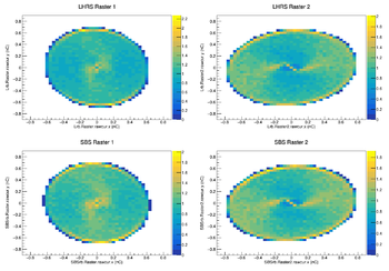
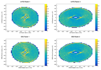
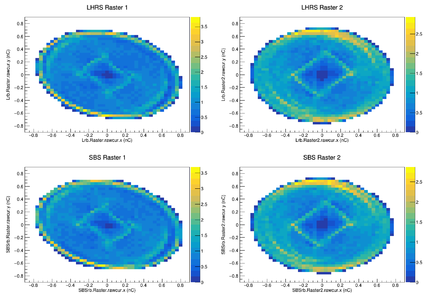
For the plots below the charge integral in nC is used (PlotInMM and SmearWithBeam are both false)
Raster checkout with the waveform used in Hall C in 2020
At the request of the GeN collaboration the waveform used during A1n/d2 in Hall C in 2020 to run the raster coils has been used to run the Hall A raster. Here is a summary of our findings:
- The Hall C waveform was loaded into the Hall A generator to run the Hall A raster
- Th carry frequency was 7751 Hz and we tried various AM frequencies: 0.5, 5, 10, 20 and 50 Hz
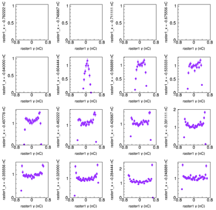
- The most uniform distributions of charge is at lower AM frequencies
- Here is a talk by Michael who wrote the code that generates the waveform for the function generator types we use in A and C (Agilent 33522A): https://userweb.jlab.org/~rom/raster/Berkowitz_12GeV_Circular_Raster_Aug18.pdf; more on the Hall A raster here: https://userweb.jlab.org/~rom/raster/
- The plots below show the charge integral from the raster coils in units of nC
- Check with GMN runs: 13709
- Latest work with Bill
- Beam line survey --> needs to be updated: IPM1H04A is actually IPM1H04. Unclear if the survey group did the IPM1H04A, they will check. If not, they will survey it before we lock up the hall.
|
}
--> Replay directory: /adaqfs/home/a-onl/gmn --> replay script: run_gen.sh (/adaqfs/home/a-onl/sbs/sbs_devel/SBS-replay/replay/replay_gen.C and /adaqfs/home/a-onl/sbs/sbs_devel/SBS-replay/replay/replay_gmn.odef; in here replay_beam.odef will secure the branches I need in the root file) |


